How to Choose the Right Harness Connector?
A Harness Connector may look like a small component, but it can determine whether power and signals reach the right place. Inside a vehicle, one connector may sit behind a dashboard, near a vibrating engine, or beneath a floor exposed to moisture. The location changes the selection criteria. So does the circuit.
The scale of modern vehicle production makes careful choices matter. OICA reported that global motor vehicle production reached about 93.5 million units in 2023 (OICA, 2023 Production Statistics). The International Energy Agency reported nearly 14 million electric-car sales that year, around 18% of all car sales (IEA, Global EV Outlook 2024). These figures point to a growing need for connectors suited to varied power loads, signal requirements, and operating environments. They do not mean every vehicle needs the same connector.
This guide explains how to assess current, voltage, pin count, wire size, sealing, temperature range, vibration resistance, and mating cycles. It also covers terminals, materials, and compatibility with the harness design. A datasheet can help, but it cannot replace checking the actual installation conditions. Small details matter. A seal that looks adequate on a workbench may not hold up where water and road salt collect. Even experienced buyers can miss that. The right choice balances verified specifications, assembly needs, and expected service conditions; when information is incomplete, that uncertainty should be recorded rather than guessed away.
Define the Harness Connector’s Purpose and Operating Requirements
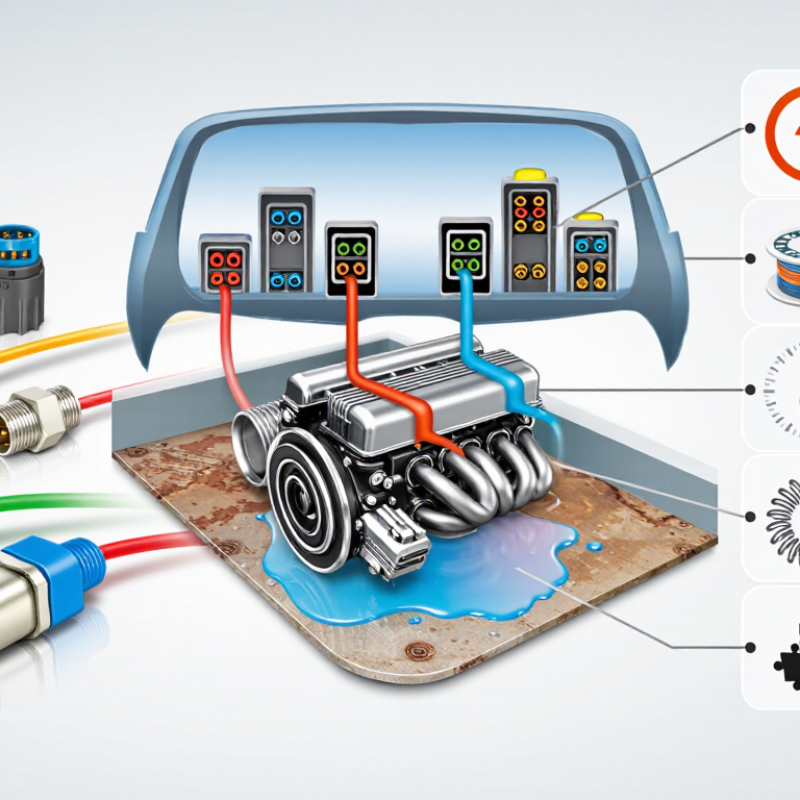
Before selecting a harness connector, define what it must connect and what the assembly needs to do. A sensor lead inside a dry cabinet has different demands from a power connection exposed to road spray. Write down the circuit count, expected current, voltage, wire size, and available space. Small details matter. A connector that fits on paper may block a nearby latch or bend wires sharply once installed.
Next, describe the operating conditions in practical terms. Note the temperature range, moisture, dust, vibration, and how often the connection will be unplugged. For example, a connector near an engine may face heat and constant movement, while a service panel may need easy access during inspections. Specify any sealing and locking needs, then check that the connector’s ratings match the real conditions, not just a best-case test. Measure twice. I have seen teams focus on pin count and overlook cable strain relief; that small omission can lead to intermittent faults.
Also consider assembly and maintenance. Can technicians identify each circuit, reach the latch, and replace a damaged terminal without disturbing neighboring wires? Confirm compatibility with the intended terminals, seals, and wire gauges as a complete system. A specification sheet helps, but a sample fit in the actual enclosure often reveals awkward routing or poor hand access. I would not assume the first layout is right; test it, inspect the wire bend, and revise the requirements before approving the connector.
Assess Electrical, Mechanical, and Environmental Conditions
How to Choose the Right Harness Connector?
Assess Electrical, Mechanical, and Environmental Conditions
Choose for the real load, not just the connector’s advertised current. Measure steady current, startup peaks, circuit length, and voltage drop at the harness end. A 10-amp rating can mislead when several loaded contacts share a crowded housing. Heat builds. Check contact resistance, wire gauge range, and terminal temperature rise under the stated test conditions. Then leave margin. A tidy bench test can still miss heat buildup in a tightly routed harness.
Mechanical fit matters just as much. Note mating cycles, cable pull direction, bend radius, and service access. IPC/WHMA-A-620 provides workmanship criteria for inspecting crimps and harness assemblies, but it does not prove a connector fits every application. Test strain relief with the actual wire and routing.
For dust and water, IEC 60529 defines IP67 as dust-tight protection and temporary immersion up to 1 metre for 30 minutes, under specified test conditions. That is not a guarantee against pressure washing, vibration, or aging seals. SAE J2030 covers heavy-duty connector testing, including environmental and mechanical stresses. Review applicable test results, not just the standard’s name.
Dirt matters. So does repeated servicing. A small trial build may reveal fit or sealing problems before tooling is fixed. Even a carefully chosen connector may need revision.
Select the Connector Type, Layout, and Contact Configuration
Choosing a harness connector starts with its environment and service needs. A sealed connector can help protect circuits exposed to splash, dust, or vibration, while an unsealed type may suit a clean, dry enclosure. Match the connector family to the space available, too. A rectangular housing can pack contacts neatly; a circular one may be easier to orient in a tight route. Fit matters. Check clearance for the latch, mating access, and cable bend radius—not just the housing dimensions on a drawing.
Next, confirm the layout and contact configuration against the actual circuit list. Count power, ground, signal, and spare positions separately. Select contact size and wire range for the expected current, conductor gauge, and temperature conditions. A high-current contact placed beside delicate signal circuits may create avoidable routing or noise concerns. Keying and cavity numbering also matter: they help prevent incorrect mating and simplify inspection. Small details count. Leave room for a suitable spare cavity only when size and sealing requirements allow it.
Before release, compare the chosen connector’s ratings with the application’s voltage, current, temperature, and vibration demands. Check whether contacts are available for the specified wire size, and verify crimp tooling and retention requirements with the technical documentation. A prototype can reveal problems a drawing misses, such as a latch blocked by nearby trim. I would not treat one successful fit as proof; repeated mating and a realistic routing check are still worthwhile.
Verify Compatibility, Ratings, and Applicable Standards
Choosing a harness connector starts with the mating parts, not appearance. Check the connector series, keying, pin count, and terminal layout against the equipment drawings. Confirm wire gauge and termination method, too. A plug can appear to fit while its pin assignments differ. That mismatch can damage equipment or create an unreliable connection. Small details matter.
Ratings need to match real operating conditions. Compare rated voltage and current with the circuit’s expected load, including startup current where relevant. Check temperature range, vibration exposure, and any required sealing or ingress protection. Ratings may change with wire size, ambient heat, or installation method, so read the applicable datasheet conditions. A connector rated for a brief peak may not support that load continuously. It is easy to overlook this.
Tips: Record the circuit requirements before comparing parts. Verify the exact mating connector and pinout, then inspect the relevant technical documentation. Check which standards apply to your product, industry, and destination; requirements vary by application and region. Don’t assume a familiar marking covers every use. If documentation is unclear, pause and confirm with a qualified engineer or compliance specialist. One extra check is less frustrating than reworking a finished harness.
How to Choose the Right Harness Connector
Verify mating compatibility, electrical ratings, environmental protection, and applicable standards before selecting a connector.
Reading the chart: IP6X denotes dust-tight protection, while IPX8 denotes protection against continuous immersion under conditions agreed between the manufacturer and user. These digits represent separate tests—not a comparative performance score. An IP rating does not confirm connector fit, pinout, voltage or current capacity, or compliance with other applicable standards.
Plan Installation, Sealing, and Long-Term Maintenance
Choosing a harness connector starts before the wires are cut. Check the circuit load, wire gauge, available space, and expected service access. A connector that fits on paper may be difficult to release beside a panel or bracket. Leave room for fingers and the correct release tool. Mark cavity positions clearly, and confirm that each terminal matches its wire size. Small details matter.
Plan sealing around the actual installation. A sealed connector can still leak if a wire seal is loose, a cavity plug is missing, or the housing is damaged. Match seals to the wire’s outer diameter, not just its conductor size. Keep mating surfaces clean, and use sealing compounds only when the connector supplier specifies them. Check the latch and seal before installation. Don’t force it. A tidy harness route also helps: avoid sharp edges, standing water, and tight bends near the connector.
Long-term maintenance should be practical, not complicated. Add accessible inspection points where moisture or vibration is likely. During service, look for cracked housings, backed-out terminals, green corrosion, and worn insulation. Pull gently on individual wires to check retention; never use the wire as a handle. Record repairs and connector changes, even if they seem minor. I would not assume a connector is trouble-free just because it passed its first inspection. Recheck it after the equipment has experienced real vibration and weather.