
For over 50 years, we have dedicated ourselves to providing Industry with best in class wire management solutions and to helping solve mission critical issues.

The needs of today’s schools and universities are changing fast. When it comes to anticipating and meeting those needs, MonoSystems is in a class of its own.

For the past five decades, we’ve made it our business to offer more value to our partners, which in turn provides greater value to their customers.
What Are the Top Types of Meter Tests?
A reliable Meter Test does more than check whether a display turns on. It asks whether the instrument measures correctly under defined conditions. For electricity meters, that can mean comparing recorded energy with a calibrated reference at different loads. The details matter. A small error may be hard to spot during a quick bench check.
The measurement principle behind this work is often summed up by physicist Lord Kelvin: “To measure is to know.” That idea guides the tests covered here, including accuracy, starting-current, no-load, and register checks. Some programs also examine insulation or other safety-related properties, where the meter design and applicable procedure determine the method. No single test tells the whole story. A meter can pass one condition and still behave differently at another load or power factor. That is worth remembering.
The following overview explains what each test checks, why technicians use it, and what results can reveal. It also distinguishes routine verification from deeper troubleshooting. In practice, proper setup matters: reference equipment, wiring, test conditions, and recorded results all affect confidence. This overview is not a substitute for a calibrated test system or the meter manufacturer’s procedure. Real testing is more exacting than a neat checklist suggests. That is part of the point.
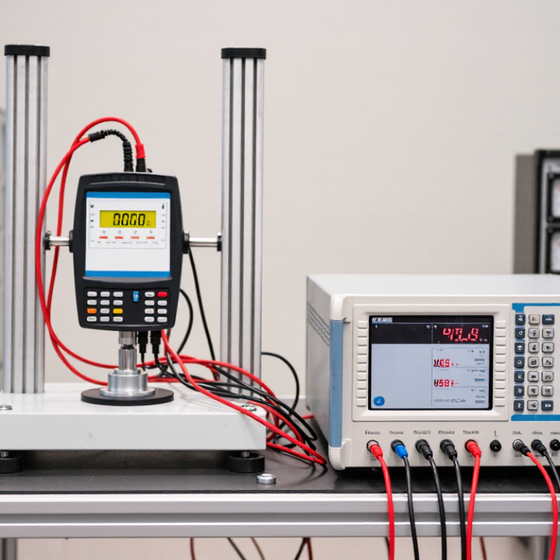
Meter Accuracy Tests and Their Measurement Principles
Meter accuracy testing compares a meter’s reading with a traceable reference under controlled conditions. For an electricity meter, technicians apply known loads and compare recorded energy with the reference value. The percentage error is the difference divided by the reference reading, multiplied by 100. A stable bench matters; loose connections can distort results.
Test points should cover more than one load. Current, voltage, and power factor can affect performance, so technicians check different operating conditions and repeat readings. IEC 62053-21 specifies a ±1% maximum permissible error for Class 1 meters at defined test points; the applicable limit depends on the test conditions. OIML R 46 also defines accuracy classes for active electrical energy meters. These figures are limits, not promises that every field reading will match a laboratory result.
Uncertainty matters, too. NIST Technical Note 1297 explains how measurement uncertainty is evaluated and reported; a coverage factor of 2 often corresponds to roughly 95% coverage under stated assumptions. In practice, a report should record the reference instrument, applied load, readings, and uncertainty. One test can look reassuring. It may still miss drift at low loads, so I would treat a single passing result as evidence, not the whole story.
| Meter Type | Test Type | Measurement Principle | Typical Test Method | Key Considerations |
|---|---|---|---|---|
| Electric energy meter | Accuracy and load-point test | The meter’s recorded energy is compared with energy calculated from calibrated voltage, current, phase angle, and test duration. | Apply controlled electrical loads at selected current and power-factor conditions; compare the meter register or pulse output with a reference standard. | Check multiple load levels, phase sequence, wiring, and power factor. Use a stable, traceable reference. |
| Water meter | Volumetric or gravimetric accuracy test | The indicated volume is compared with a reference volume, or with the collected water’s mass converted to volume using water density at the test temperature. | Pass a measured quantity of water through the meter at controlled flow rates, then compare the meter reading with a calibrated tank or weighing system. | Control flow stability, air removal, water temperature, and leakage. Test points should cover the meter’s intended operating range. |
| Gas meter | Prover comparison test | The meter’s registered gas volume is compared with a known reference volume delivered by a calibrated prover. | Run gas through the meter and prover at controlled flow rates; compare their volume readings, applying relevant pressure and temperature corrections when required. | Check for leaks and pulsation, and account for gas pressure, temperature, and test-gas conditions. |
| Liquid flow meter | Reference-meter or gravimetric comparison | The test meter’s flow or accumulated quantity is compared with a calibrated reference meter or with collected mass converted to volume. | Operate the test and reference meters in a stable flow loop, or collect and weigh the fluid over a measured interval. | Allow flow to stabilize; consider fluid properties, temperature, installation effects, and the reference instrument’s uncertainty. |
| Heat meter | Component and energy-calculation test | Thermal energy is calculated from the measured fluid flow and the temperature difference between supply and return, using the fluid’s thermal properties. | Check the flow sensor and temperature sensors against references, then verify that the calculator produces the expected energy from known inputs. | Verify sensor pairing, installation orientation, temperature-sensor placement, and correct fluid settings. |
| Pressure gauge | Pressure comparison and hysteresis test | The gauge indication is compared with a calibrated pressure reference at increasing and decreasing pressure points. | Apply pressure using a suitable pressure source and reference instrument; record readings across the range in both directions. | Check zero return, repeatability, hysteresis, leaks, and whether the reference and gauge use the same pressure basis. |
| Common error calculation: Percentage error = [(meter indication − reference value) ÷ reference value] × 100. Interpret results against the applicable meter specification and test procedure; measurement uncertainty should also be considered. | ||||