| Cable Volume |
Select a tray width that accommodates the calculated cable area without excessive crowding. |
Common widths: 150, 300, 450, 600, 750 and 900 mm. |
300–600 mm for most building and industrial runs; 750–900 mm for high-density routes. |
Allow space for future circuits while avoiding unnecessary oversizing and added steel cost. |
| Cable Fill |
Maintain separation and preserve room for installation, inspection and heat dissipation. |
A planning target of approximately 40–60% usable width is commonly adopted; verify applicable electrical rules. |
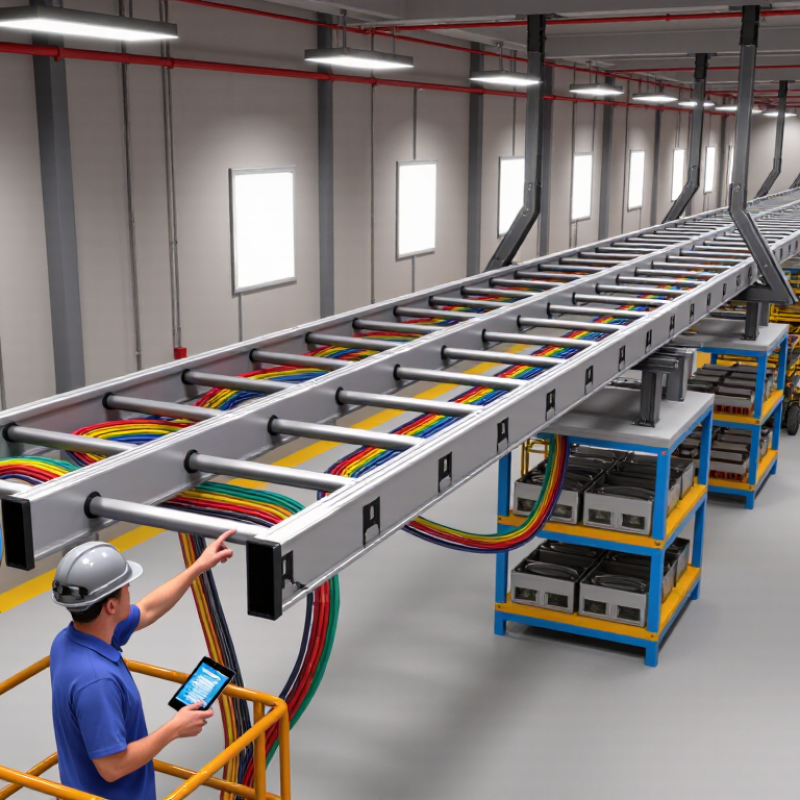
A wider ladder tray where projected growth exceeds the initial cable bundle. |
Moderate fill reduces rework and makes future cable additions easier. |
| Support Span |
Match the tray’s tested load rating to the distance between supports. |
Typical support spans: 1.5, 2.0, 2.4 and 3.0 m; final capacity depends on the specific system. |
A heavy-duty tray for long spans or concentrated cable loads. |
A verified load table is more important than nominal sheet thickness alone. |
| Working Load |
Include cable weight, accessories, covers, ice or dust where applicable, and installation loads. |
Many systems are published in load classes from roughly 75 to 300 kg/m, but ratings vary by width and span. |
Use the next tested load class above the calculated design load. |
A safety margin helps prevent deflection, cable damage and premature replacement. |
| Material |
Choose according to corrosion exposure, mechanical demands, weight limits and project environment. |
Carbon steel, pre-galvanized steel, hot-dip galvanized steel, aluminum and stainless steel. |
Galvanized steel for general industrial use; aluminum for weight-sensitive areas; stainless steel for severe corrosion. |
The lowest purchase price may not provide the lowest whole-life cost in corrosive locations. |
| Corrosion Exposure |
Assess humidity, salt spray, chemicals, wash-down procedures and outdoor exposure. |
Indoor dry, indoor humid, outdoor urban, coastal and chemical-processing environments require progressively stronger protection. |
Hot-dip galvanized or stainless construction for outdoor and high-moisture service. |
Specify coating and post-fabrication protection; cut edges and drilled areas can become corrosion initiation points. |
| Rung Spacing |
Balance cable support, bend radius, ventilation and ease of cable tying. |
Common rung spacing is approximately 225–300 mm. |
Closer spacing for smaller or heavier cables; wider spacing for lightweight power and control cables. |
Appropriate spacing reduces the need for extra cleats and improves cable organization. |
| Cable Type |
Consider cable diameter, minimum bend radius, shielding, segregation and heat generation. |
Separate power, control, instrumentation and communication circuits where project rules require it. |
Use multiple tiers or dividers when different circuit categories must be segregated. |
Correct segregation improves reliability and reduces electromagnetic interference risks. |
| Fittings and Accessories |
Confirm compatibility of bends, tees, crosses, reducers, splices, covers and supports. |
Common horizontal bend angles: 30°, 45°, 60° and 90°; vertical inside and outside bends are also available. |
A complete modular system with matching connectors and adjustable supports. |
Standardized accessories reduce installation time and simplify future modifications. |
| Earthing and Bonding |
Provide electrical continuity and bonding in accordance with the applicable installation code. |
Use listed bonding jumpers or approved splice arrangements where continuity is not assured. |
A metallic system with documented continuity and grounding provisions. |
Good bonding supports fault-current paths and reduces inspection problems. |
| Standards and Testing |
Require evidence of structural and electrical performance from a recognized standard or project specification. |
Common references include IEC 61537 and NEMA VE 1, depending on the project location. |
A system with published load, deflection, corrosion and continuity data. |
Traceable test documentation improves approval, maintenance and replacement decisions. |
| Installation Conditions |
Check access, lifting limits, ceiling clearance, seismic conditions and coordination with other services. |
Lightweight sections are easier to handle; long sections can reduce splice count but may require more lifting space. |
Use manageable section lengths and adjustable supports in congested areas. |
Lower labor hours can outweigh a small difference in material cost. |
| Future Expansion |
Reserve capacity for additional cables, route changes and new equipment. |
A planning allowance of 20–30% spare space is commonly used, subject to project requirements. |
Select the next practical width or install a dedicated spare route. |
Planned expansion capacity reduces shutdowns, demolition and emergency tray additions. |