Top 10 Types of Cable Tray Brackets for Buyers

Cable routing rarely gets attention until a tray sags, clashes with a pipe, or blocks access. Yet the bracket behind each run affects load support, alignment, and maintenance clearance. For buyers, choosing cable tray brackets is not just a matter of price. Span, tray type, installation surface, corrosion exposure, and expected cable load all shape the right choice.

The scale of electrical infrastructure is growing. The International Energy Agency’s Electricity 2024 report projects global electricity demand growth of about 3.4% annually through 2026. Meanwhile, Uptime Institute’s 2024 Global Data Center Survey identifies power availability as a continuing concern for data center operators. These reports do not prescribe bracket designs, but they underline why dependable, well-planned cable support matters in demanding facilities.

This guide compares ten common bracket types, from wall-mounted and cantilever supports to trapeze and adjustable designs. It considers where each option fits, what buyers should verify, and which trade-offs deserve a closer look. Check material, finish, rated load, fixing method, and compatibility with the tray system. Small details count. A bracket that suits a light indoor run may be a poor choice near vibration, moisture, or heavy cable bundles. Product specifications should be checked against the actual installation; catalog language alone is not enough. There is no universal best bracket, and that is worth remembering.
Top 10 Types of Cable Tray Brackets for Buyers

Define bracket functions and the NEC 392.30 support limit of 6 ft (1.83 m)

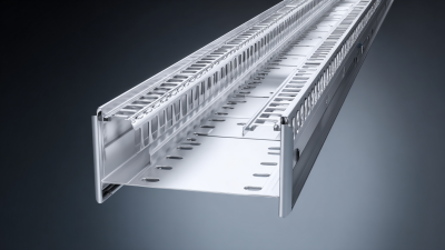
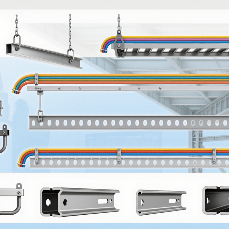
Cable tray brackets carry dead load, cable weight, and forces from installation or maintenance. Common options include wall-mounted brackets, cantilever arms, trapeze supports, single-rail supports, beam clamps, ceiling hangers, strut-channel brackets, riser supports, underfloor supports, and adjustable seismic braces. Each suits a different mounting surface or load path. A cantilever arm leaves the tray accessible from one side, while a trapeze holds it between two threaded rods. Choose hardware compatible with the tray material and the building structure, not just the tray width.

Spacing matters. A 6-ft (1.83-m) support interval is a conservative design target, but it should not be presented as a universal NEC 392.30 maximum. Requirements can vary by NEC edition, tray listing, manufacturer instructions, and project conditions; confirm the applicable rules with the authority having jurisdiction. Keep supports close to tray joints when the system instructions require it, and add support where turns, vertical transitions, or heavy cable loads increase stress. Small details matter. A tray may look level while a lightly fastened bracket flexes under load. That is easy to overlook. Check fasteners, anchor capacity, and actual span on site, and document any spacing changes before cables are installed.

Top 10 Types of Cable Tray Brackets for Buyers

Bracket functions and a general NEC 392.30 support-spacing reference

How to read the chart: The bars repeat the 6 ft (1.83 m) reference for comparison only. This is not a bracket load rating or a guaranteed span for every installation. Confirm the applicable NEC edition, cable tray type, loading, and manufacturer’s installation instructions; closer support may be required.

Bracket types and typical functions

  1. Wall cantilever bracket: Projects from a wall to support a tray along a wall.
  2. Trapeze support: Suspends tray from two rods or hangers, commonly for wider trays or multiple runs.
  3. Center-hung bracket: Suspends a tray from a central rod where the support system is designed for that arrangement.
  4. Ceiling-mounted bracket: Attaches tray supports directly to a suitable ceiling structure.
  5. Strut-channel bracket: Uses structural channel to provide an adjustable mounting point for tray supports.
  6. Beam-clamp support: Connects a tray support to a compatible structural beam without drilling the beam.
  7. Threaded-rod hanger: Suspends tray supports from overhead structure using threaded rods.
  8. Riser support: Supports tray at vertical transitions and helps manage loads along the riser.
  9. Underfloor support: Raises and supports tray below a raised floor or within an underfloor service space.
  10. Roof support: Supports tray above a roof while distributing loads through a suitable roof-support system.

Identify wall, cantilever, trapeze, ceiling-hanger, and beam-clamp brackets

Top 10 Types of Cable Tray Brackets for Buyers

Bracket choice starts with load direction and the supporting structure. Wall brackets keep trays close to masonry or steel walls, useful in corridors where floor clearance matters. Cantilever brackets project from one side, leaving the route open underneath. They need secure anchors; a long arm increases leverage. Trapeze brackets suspend trays between two threaded rods, spreading loads across paired supports. They suit wide runs and multiple tray tiers. Check rod spacing and vibration, not just tray width. Small details matter.

Ceiling-hanger brackets attach overhead, preserving wall space but requiring careful alignment with beams and services. Beam clamps attach to suitable structural flanges without drilling; verify flange thickness, load rating, and slippage risk. NEMA VE 2 installation guidance places supports within 600 mm (2 ft) of expansion splice plates. That figure highlights how support placement affects joint movement. NEMA VE 1 load/span tables pair tray ratings with support spans, so match brackets to the tested tray system and actual cable weight. Real sites are messier. Allow for cable growth, bends, and maintenance access; I would still recheck the layout after field routing.

Compare strut-channel, center-hung, riser, floor, and adjustable brackets

Top 10 Types of Cable Tray Brackets for Buyers

Strut-channel brackets suit installations that need flexible mounting points. Installers can reposition the tray as routes change, though loose fittings may allow movement. Center-hung brackets suspend trays from overhead supports and keep walls clear. Check rod spacing and tray loading; a crowded span can sag. Riser brackets support vertical sections where cables move between floor levels. Their position and fastening need careful attention, especially near bends. Floor brackets hold trays above a slab, leaving room for cleaning and inspection. Adjustable brackets help align trays around uneven surfaces or existing services. They save time, but too many adjustments can weaken a tidy layout. Fit matters.

Tips: Compare the tray width, expected cable load, support spacing, and mounting surface before choosing. For a real installation, follow the bracket maker’s load data and applicable project requirements. Check clearances with a tape measure, not just a drawing. A bracket that looks suitable on paper may still obstruct a pipe or access panel.

Match bracket capacity to NEMA VE 1 load classes and tray support spans

A cable tray bracket is only suitable when its rated capacity matches the tray’s load class and support span. NEMA VE 1 provides load classifications based on specified loading and support conditions; check the applicable class and span in the tray system’s documentation. A class alone does not tell you whether a bracket, anchor, or wall can carry the installation.

Include the tray’s own weight, cable weight, and a realistic allowance for future additions. Then compare the total load and support spacing with the bracket’s published rating. A short cantilever arm may work on a close support span, while a longer span can increase bending forces and deflection. Details matter. Check bracket orientation, fasteners, substrate, and any local loading conditions, such as a heavy cable bundle concentrated on one side. Don’t assume every support shares the load evenly.

On site, measure actual spacing and inspect the mounting surface before choosing from the ten common bracket styles. A paper layout can miss a beam, conduit, or uneven wall. That happens. If the installed span differs from the design, reassess the capacity rather than relying on appearance; consult a qualified engineer when loads or conditions fall outside documented ratings.

Top 10 Types of Cable Tray Brackets for Buyers — Match Bracket Capacity to NEMA VE 1 Load Classes and Tray Support Spans
Bracket Type Typical Configuration Common Application Capacity and Span Selection Considerations
1. Wall-Mounted Cantilever Bracket Horizontal arm fixed directly to a structural wall or column. Single-tier tray runs along building walls. Check the arm’s allowable load at the actual projection and the wall-anchor capacity. Confirm the tray’s specified NEMA VE 1 load class and support span; do not assume a longer arm has the same capacity as a shorter one.
2. Heavy-Duty Wall Cantilever Bracket Reinforced or braced cantilever arm attached to a structural surface. Wider or more heavily loaded trays where a standard arm is insufficient. Compare the bracket’s published load rating and deflection limit with the calculated load at each support. Verify the substrate, anchors, arm projection, and tray-span design as a complete load path.
3. Trapeze Support Bracket Horizontal cross-member suspended from two rods or other engineered hangers. Overhead tray routes, especially where multiple trays share a support frame. Check cross-member bending, hanger tension, rod spacing, and connection capacity. The combined load of all supported trays and accessories must be considered against the specified tray load class and span.
4. Single-Rod Hanger Bracket Tray-support fitting suspended from one threaded rod or approved hanger. Light-duty or space-constrained overhead installations, when permitted by the tray system design. Confirm that the fitting is designed for the tray type and loading arrangement. Check rod capacity, attachment details, and any limits on tray width or loading; use the specified support spacing rather than choosing spacing from the bracket name alone.
5. Floor-Mounted Pedestal Support Vertical post or pedestal with a tray-support head, fixed to a floor or base. Raised-floor areas, equipment rooms, and routes where overhead suspension is unavailable. Verify post stability, base-plate and anchor capacity, and floor or slab suitability. Include lateral loads and the tray’s loaded span in the design review.
6. Adjustable Strut-Channel Bracket One or more strut-channel members assembled with compatible fittings. Installations needing adjustable width, elevation, or multi-tier support. Capacity depends on channel section, orientation, unsupported length, fittings, and fasteners. Use published component ratings for the exact assembly and check the combined tray loads at the selected support span.
7. Beam-Clamp Support Bracket Bracket or hanger attached to a structural beam using an approved beam clamp. Overhead supports where drilling or welding to the beam is not allowed. Confirm compatibility with the beam shape and flange thickness, clamp orientation, and allowable load. The beam itself and the complete attachment must be suitable for the design load.
8. Vertical-Riser Support Bracket Clamps or support plates that secure tray sections along a vertical route. Vertical tray runs and transitions between floors or elevations. Account for the vertical cable load, support intervals, and the tray manufacturer’s installation requirements. Verify that the bracket and fasteners restrain the tray without damaging it.
9. Underfloor or Raised-Floor Support Bracket Low-profile pedestal or frame installed beneath a tray run. Underfloor cable distribution and raised-access-floor spaces. Check support height, stability, anchorage, and clearance. Confirm the floor system can carry the transferred load and that the chosen tray span matches the design load class.
10. Seismic or Lateral-Bracing Bracket Brace assembly that restrains tray-support frames against specified lateral movement. Projects requiring engineered restraint for seismic or other lateral loads. Bracing is not a substitute for gravity-load support. Follow the project’s applicable seismic design criteria and verify the brace, connections, supporting structure, and tray system as an engineered assembly.
Buyer’s design note: NEMA VE 1 load-class and span selection applies to the cable tray system; a bracket’s capacity is not established by the tray class alone. Confirm the project-specified tray loading and support span, then check the bracket, fasteners, anchors, supporting structure, and installation details using the applicable manufacturer data and project requirements. Allow for cable weight, tray weight, accessories, and any other specified loads.

Verify load testing and bracket selection against IEC 61537 requirements

Top 10 Types of Cable Tray Brackets for Buyers

Bracket choice affects how a tray carries cable weight, especially at corners and long spans. IEC 61537:2023 sets test methods for cable tray and ladder systems, including declared safe working load (SWL). A test result applies to its stated support span and setup. It is not a universal load rating. Check the report for the tested span, loading arrangement, bracket spacing, and measured deflection. A neat-looking bracket can still flex when the tray is full.

Tips: Match the bracket type to the mounting surface and tray geometry. Wall cantilever brackets suit wall runs; trapeze supports work for suspended routes. Ask for test evidence covering the actual bracket and support configuration, not just a similar product. Check anchor capacity separately. Small detail. It matters.

Before buying, compare the rated load with cable weight, tray weight, and likely future additions. Confirm whether the report tests a single bracket or a complete support arrangement. For corrosive areas, verify material and coating details alongside mechanical performance. Site conditions are rarely perfect; uneven walls and improvised spacing can undermine otherwise sound test data. If the supplier cannot provide a clear load-deflection report tied to IEC 61537, treat the rating cautiously.